

A Control Flow Graph (CFG) is a graphical representation of all possible execution paths in a program. It is mainly used in white-box testing to analyze the program's control structure and identify different execution paths for effective test case design.
- Represents the flow of control between program statements.
- Helps identify independent execution paths.
- Widely used for white-box testing and code analysis.
Working of a Control Flow Graph
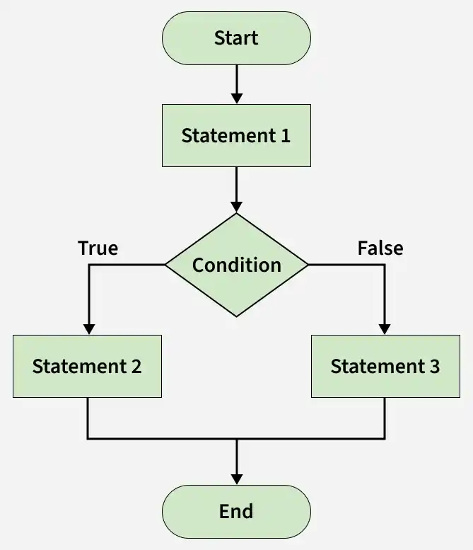
- Start: This is the Entry Node, where program execution begins.
- Statement 1: Represents the first instruction or block of code executed after the program starts. Since there is only one outgoing path, execution continues directly to the next node.
- Condition (Decision Node): This diamond-shaped node represents a conditional statement, such as an if or if-else statement. The condition determines which execution path the program follows.
- True Branch: If the condition evaluates to True, the program executes Statement 2.
- False Branch: If the condition evaluates to False, the program executes Statement 3.
- End: After executing either Statement 2 or Statement 3, both execution paths merge into a single Exit Node, where program execution ends.
CFG Representation for Different Control Structures
A Control Flow Graph can be drawn for different programming constructs to represent how control moves during program execution.
1. If-Else Statement

- The test expression is evaluated first.
- If the condition is True, the if block is executed.
- If the condition is False, the else block is executed.
- Both execution paths merge and continue with the next statement.
2. While Loop
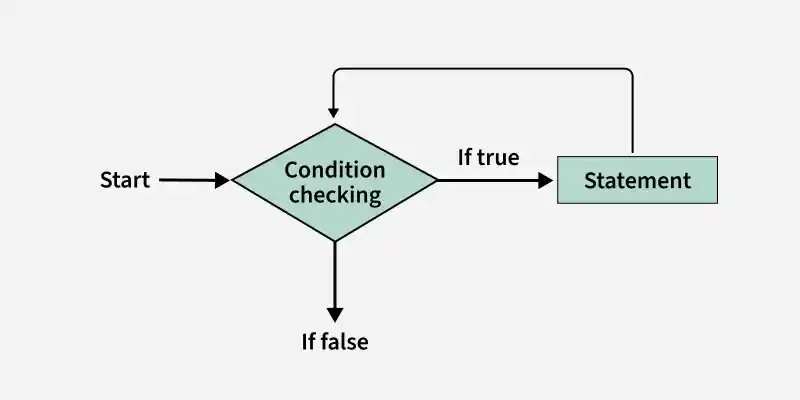
- The loop condition is checked before executing the loop body.
- If the condition is True, the loop body is executed.
- After execution, control returns to the condition for the next iteration.
- If the condition is False, the loop terminates.
3. Do-While Loop
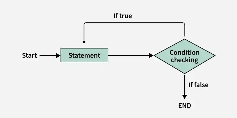
- The loop body is executed before checking the condition.
- The condition is evaluated after each iteration.
- If the condition is True, control returns to the loop body.
- If the condition is False, the loop terminates.
- The loop body is executed at least once.
4. For Loop
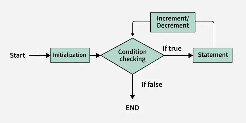
- The loop begins with initialization.
- The condition is checked before each iteration.
- If the condition is True, the loop body is executed.
- The increment/decrement operation is performed after each iteration.
- Control returns to the condition for the next iteration.
- If the condition is False, the loop terminates.
Example
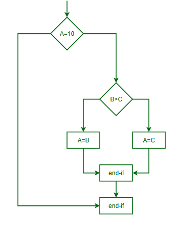
If A = 10 then
If B > C then
A = B
Else
A = C
End IfEnd If
Print A, B, C
Flowchart of above example will be:
Explanation of the Control Flow Graph
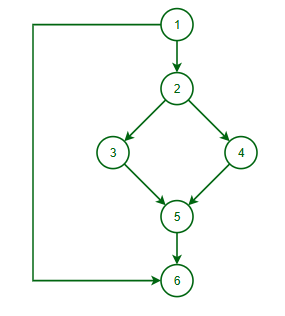
- Node 1: Program execution begins.
- Node 2: Checks whether A = 10.
- Node 3: If A = 10 is True, checks whether B > C.
- Node 4: If B > C is True, executes A = B.
- Node 5: If B > C is False, executes A = C.
- Node 6: Both branches merge and execute Print A, B, C.
- Node 7: Program execution ends.
Control Flow Graph of above example will be:
Symbols Used in Control Flow Graph
A Control Flow Graph (CFG) uses simple symbols to represent the flow of execution in a program. Each symbol has a specific purpose in illustrating how control moves between different parts of the code.
| Symbol | Meaning | Description |
|---|---|---|
| (Circle) O | Node / Basic Block | Represents a statement or a group of sequential statements executed without branching. |
| (Arrow) -> | Edge / Control Flow | Shows the direction of execution from one node to another. |
| Start | Entry Node | Indicates the point where program execution begins. |
| End | Exit Node | Indicates the point where program execution terminates. |
| ◇ (Diamond) | Decision Node | Represents a conditional statement such as if, else, switch, or loop conditions with multiple execution paths. |
Applications of Control Flow Graph
- Designing white-box test cases.
- Calculating Cyclomatic Complexity.
- Identifying independent execution paths.
- Detecting unreachable or dead code.
- Supporting compiler optimization and program analysis.
- Assisting in debugging and code maintenance.
Advantage of CFG
- Clearly visualizes the program's execution flow.
- Helps identify independent execution paths for testing.
- Supports cyclomatic complexity calculation.
- Detects unreachable or dead code.
- Simplifies debugging by tracing control flow.
Limitations of Control Flow Graph (CFG)
- Does not represent data flow or variable values.
- Becomes complex for large programs.
- Focuses only on control flow, not output correctness.
- Cannot represent dynamic runtime behavior or external interactions.
- Requires additional effort to construct and maintain for large applications.
