

8051 microcontrollers are mainly used to speed up our tasks because they are very easy to use and they are also fast to complete tasks easily. These microcontrollers have one main feature which is Timers and counters. This feature is widely used in microcontrollers to measure the time and as well as to count the events or tasks. By learning about these timers and counters ,we can make good embedded systems.
8051 Timers and Counters
Timers and counters are one of the best feature that is provided by microcontrollers. Timers are used to measure the time and for creating time delays . Counters are used to count the events or tasks that are taking place outside the microcontrollers. We can setup these timers and counters with the microcontrollers to make our tasks in different ways to fit in different tasks.
Types
The 8051 microcontroller mainly has two timers they are Timer 0 and Timer 1. These are used as both timers as well as counters. They are 16-bit long but the format of the microcontroller is 8-bit, due to that the Timers or counters are divided into two 8-bit parts a low byte and a high byte.
Timer 0 (T0)
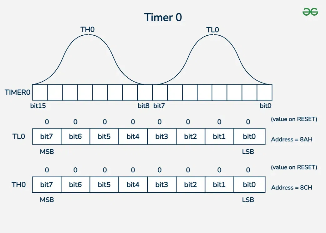
One of the main timers/counters in the 8051 microcontroller, used for doing timing operations and counting events. It is divided into two 8-bit registers they are TL0 (Timer 0 Low byte) and TH0 (Timer 0 High byte). By combining both, these form a 16-bit timer/counter.
TL0 (Timer 0 Low Byte)
- TL0 is the lower 8-bit register of Timer 0.
- It stores the lower byte of the count value.
- When timer 0 functions as a 16-bit timer, TL0 increases first, and TH0 increases by one following an overflow (when 255 is achieved).
TH0 (Timer 0 High Byte)
- TH0 is the upper 8-bit register of Timer 0.
- It stores the higher byte of the count value.
- When TL0 overflows, Timer 0 can count up to 65,535 (FFFFH) before spilling since TH0 is increased.
Structure of Timer 0
Timer 1 (T1)
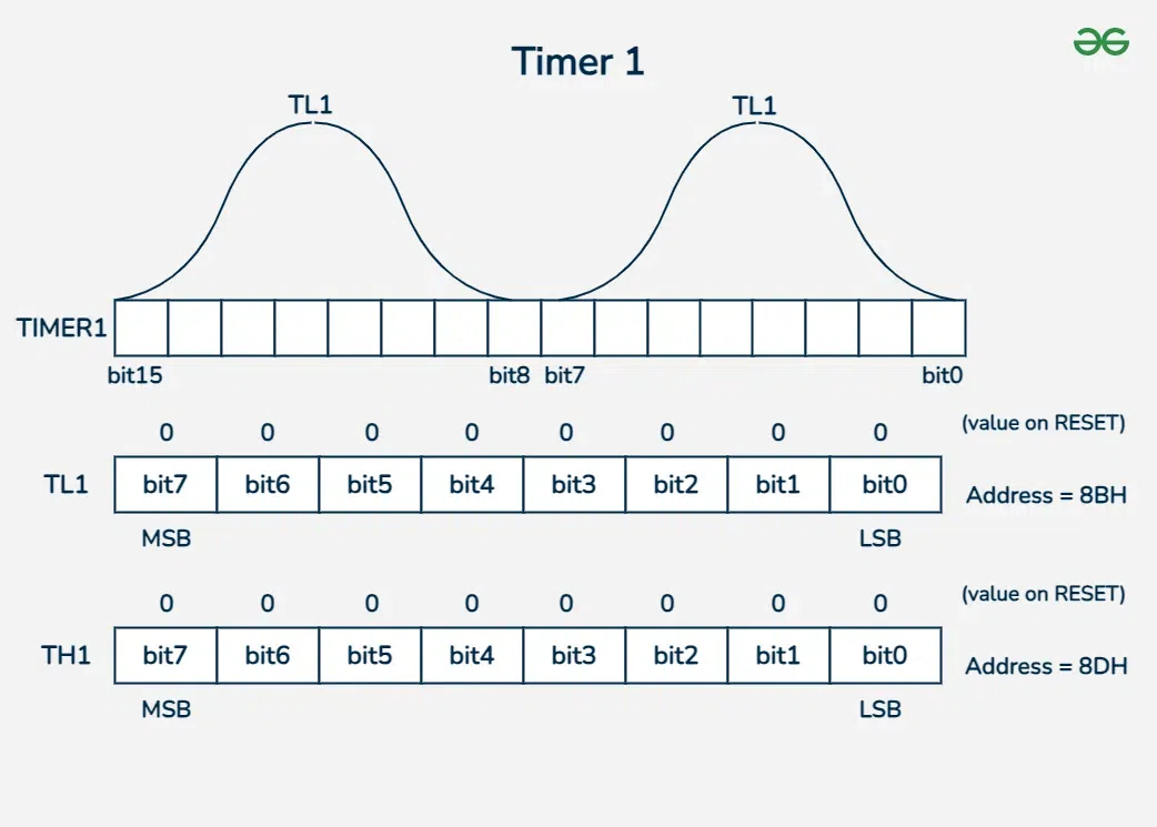
Timer 1 is also one of the main timers/counters in the 8051 microcontroller, used for doing timing operations and counting events. It is also divided into two 8-bit registers they are TL1 (Timer 1 Low byte) and TH1 (Timer 1 High byte). By combining both, these form a 16-bit timer/counter
TL1 (Timer 1 Low Byte)
- Timer 1's bottom 8-bit register is designated as TL1.
- It contains the count value's bottom byte.
- When using a 16-bit timer, TL1 increases first and then TH1 by 1 once TL1 reaches its maximum value of 255.
TH1 (Timer 1 High Byte)
- Timer 1's upper 8-bit register is designated as TH1.
- It contains the count value's higher byte.
- When TL1 overflows, TH1 increments, allowing Timer 1 to count up to 65,535 (FFFFH) before overflowing.
Structure of Timer 1
Timer Control Registers
TCON and TMOD are the special function registers in the 8051 microcontroller. These are used to control the timers and counters.
- TCON (Timer Control Register): The timers' start and stop are aided by this register. It additionally indicates whether the timer is done counting.
- TMOD (Timer Mode Register): The timers' mode is adjusted using this register. It selects whether the timers will record events occurring outside of the microcontroller or record time.
So, to make the timers and counters work, you need to set up TCON and TMOD properly. In this way, you can use the timers to measure time or count events, depending on what you need for your task.
TCON (Timer Control Register)
The 8051 microcontroller has a unique function register called the TCON (Timer Control Register). In order to provide precise output, timers and counters are controlled by it. The data in the registers may overflow if these timers and counters are not under control. Thus, the TCON is utilized to control the timers and counters.
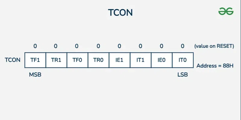
Structure of TCON
The TCON register is an 8-bit register, where each bit has a specific function:
Bit | Bit Name | Description |
|---|---|---|
7 | TF1 (Timer 1 Overflow Flag) | Set to 1 when Timer 1 overflows else 0. |
6 | TR1 (Timer 1 Run Control Bit) | Set to 1 to start Timer 1, and set to 0 to stop Timer 1. |
5 | TF0 (Timer 0 Overflow Flag) | Set to 1 when Timer 0 overflows else 0. |
4 | TR0 (Timer 0 Run Control Bit) | Set to 1 to start Timer 0, and set to 0 to stop Timer 0. |
3 | IE1 (Interrupt 1 Edge Flag) | Set to 1 when an external interrupt 1 occurs else 0. |
2 | IT1 (Interrupt 1 Type Control Bit) | Set to 1 to configure external interrupt 1 as edge-triggered, and set to 0 for level-triggered. |
1 | IE0 (Interrupt 0 Edge Flag) | Set to 1 when an external interrupt 0 occurs else 0. |
0 | IT0 (Interrupt 0 Type Control Bit) | Set to 1 to configure external interrupt 0 as edge-triggered, and set to 0 for level-triggered. |
TMOD (Timer Mode Register)
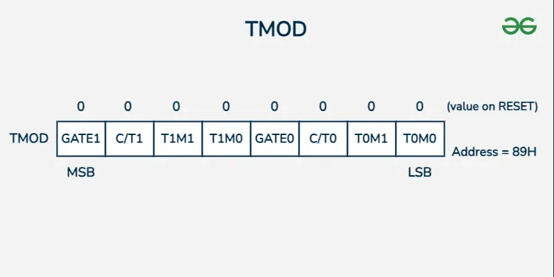
Special function register in the 8051 microcontroller. Timer 0 and Timer 1 are the modes of operation that it is utilized to set. Whether a timer or counter needs to be set, it is done so using this register. The structure in detail is displayed below.
Structure of TMOD Register
The eight bits of the TMOD register are split into two sections: Timer 0 is controlled by the lower four bits, and Timer 1 is controlled by the upper four bits. Similar bit fields in each component set the timers' mode and behavior.
Bit | Bit Name | Description |
|---|---|---|
7 or 3 | Gate (0 or 1) | Gate Control Bit |
6 or 2 | C/Tx | Counter/Timer Select Bit |
5 or 1 | TxM1 | Timer Select Bits for Mode1 |
4 or 0 | TxM0 | Timer Select Bits for Mode0 |
- GATE (Gate Control Bit): When set to 1, the timer/counter is enabled only while the INT pin is high and TR control bit is set. When cleared to 0, the timer is enabled whenever the TR control bit is set.
- C/T (Counter/Timer Select Bit): When set to 1, the timer operates as a counter (counts external events). When cleared to 0, it operates as a timer (measuring time).
- M1 and M0 (Mode Select Bits):
M0 | M1 | Mode | Description |
|---|---|---|---|
0 | 0 | Mode 0 | 13-bit Timer mode (8 Bit of THx and 5 Bit of TLx). |
0 | 1 | Mode 1 | 16-bit Timer mode. |
1 | 0 | Mode 2 | 8-bit Auto-reload mode (TLx reload with the THx value each time when TLx overflows). |
1 | 1 | Mode 3 | Split Timer mode - Split 16 bit timer into two 8 bit timers(THx and TLx). |
Timer Counter Modes
The modes are divided into four as shown below.

Timer Mode
The Modes which are used to create time delays , measure time intervals, or generate precise time-based signals are known as Timer modes. The modes that acts as timers are given below,
Mode 0: 13-bit Timer Mode
- Description: In Mode 0, 0 or 1 timer functions as a 13-bit timer. It counts from 0 to 8191 counts, or from 0000H to 1FFFH. It makes use of all eight bits of TH0 or TH1, and five bits of TL0 or TL1.
- Working Principle: TLx counts in steps of 0 to 31, resets to 0, and then increases THx. Out of the two timer bytes, only 13 bits are used.
- Usage: Because of the narrow count range of 8192 values, it is rarely utilized.
- Example: It is used for Generating Short Delays

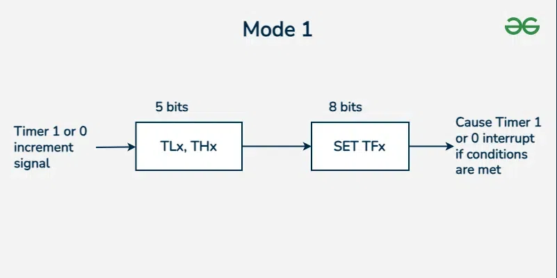
Mode 1: 16-bit Timer Mode
- Description: Timer 0 and Timer 1 are set up as 16-bit timers in Mode 1. They use the 0000H to FFFFH count range (0 to 65535).
- Working Principle: TLx uses all 16 bits to count from 0 to 255, resets to 0, and then increases THx.
- Usage: Because of its larger range of values, it is frequently utilized for a variety of timing jobs.
- Example: It is used for Timing Events or Generating PWM Signals.
Counter Mode
The Modes which are used to count the number of events or pulses that are happening outside the microcontroller are known as Counter modes. The modes that acts as counters are given below
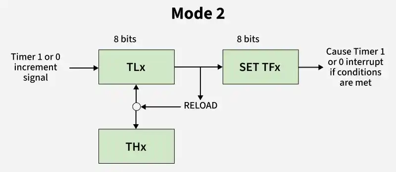
Mode 2: 8-bit Auto-Reload Mode
- Description: The configuration of Timer 0 in Mode 2 is an 8-bit auto-reload timer. It counts from 00H to FFH (0 to 255) and then loads the starting value automatically.
- Working Principle: TLx starts at 0 and increases to 255, but instead of returning to 0, it reloads with the value from THx.
- Usage: Good for jobs like setting baud rates, when the timer needs to continuously reload with a set value.
- Example: Used for Frequency Measurement.
Mode 3: Split Timer Mode
- Description: Timer 0 is divided into two 8-bit timers in Mode 3, which enables Timer 0 to function as two independent timers while Timer 1 continues to function as a 16-bit timer as usual.
- Working Principle: Both timers separately count from 0 to 255, then overflow back to 0. The control bits of Timer 1 are connected to TH0.
- Usage: helpful when two independent timers are required.
- Example: Used in Real-time Clock with Alarm Functionality.

