


imu和mems的差别
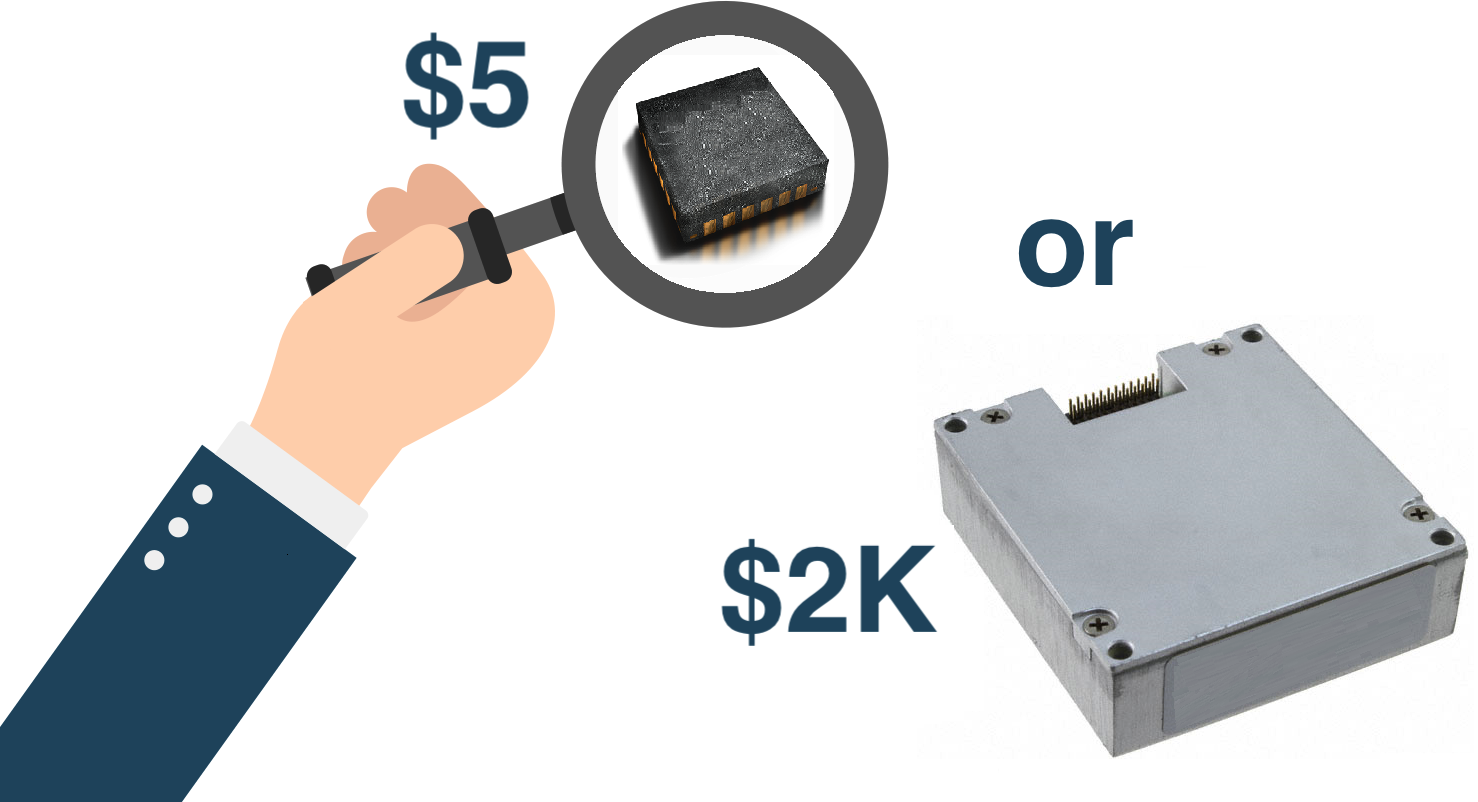
When it's necessary to evaluate the orientation angles of an object you may have the question — which MEMS sensor to choose. Sensors manufacturers provide a great amount of different parameters and it may be hard to understand if the sensor fit your needs.
当需要评估对象的定向角时,您可能会遇到问题-选择哪种MEMS传感器。 传感器制造商提供了大量不同的参数,可能很难理解传感器是否满足您的需求。
Brief: this article is the description of the Octave/Matlab script which allows to estimate the orientation angles evaluation errors, derived from MEMS accelerometers and magnetometers measurements. The input data for the script are datasheet parameters for the sensors. Article can be useful for those who start using MEMS sensors in their devices. You can find the project on GitHub.
简介:本文是对Octave / Matlab脚本的描述,该脚本允许估计来自MEMS加速度计和磁力计测量值的取向角评估误差。 脚本的输入数据是传感器的数据表参数。 对于那些开始在其设备中使用MEMS传感器的人来说,这篇文章可能会很有用。 您可以在GitHub上找到该项目。
We are using the following conditions:
我们使用以下条件:
We're going to estimate the attitude of the stationary object.
我们将估计静止物体的姿态。
为什么? (Why?)
The orientation of the moving object cannot be calculated reliably by using following formulas and you'll have to use more sophisticated algorithms.使用以下公式无法可靠地计算出移动物体的方向,您将不得不使用更复杂的算法。- We will use measurements of the MEMS accelerometers and magnetometers to evaluate orientation angles. 我们将使用MEMS加速度计和磁力计的测量值来评估方向角。
1.一点理论 (1. A bit of theory )
定向角 ( Orientation angles )
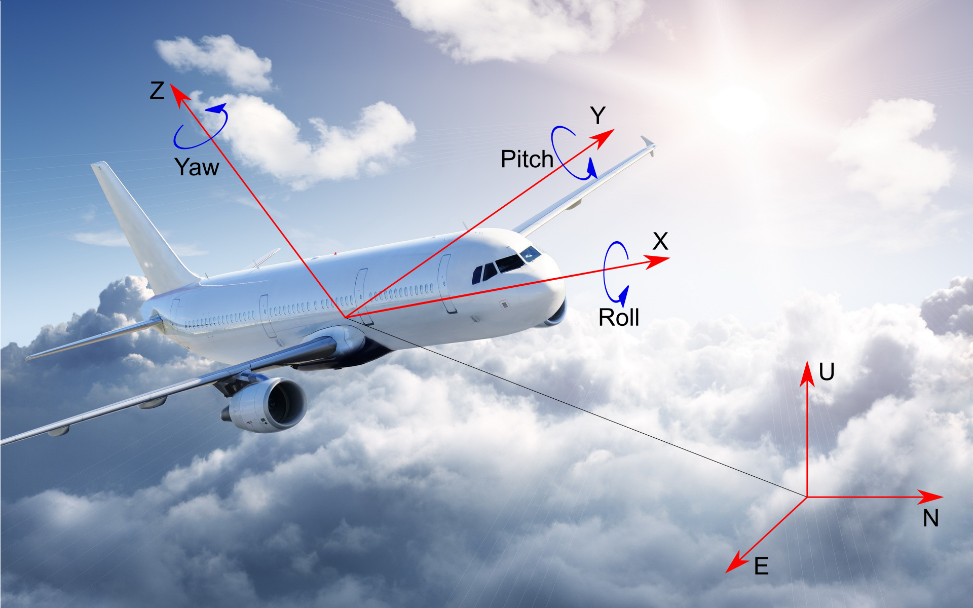
Here, orientation angles is the three Euler Angles — Roll, Pitch and Yaw. They connect the body frame coordinate system XYZ and the local coordinate system East-North-Up (ENU). The Roll, Pitch and Yaw angles denote the rotation that the XYZ axes must make in order to move in the ENU axis.
在这里,定向角是三个欧拉角-滚动角,俯仰角和偏航角。 它们连接车身框架坐标系XYZ和局部坐标系East-North-Up(ENU)。 旋转角,俯仰角和偏航角表示XYZ轴必须旋转才能在ENU轴上移动。
Accordingly, zero angles mean that the X axis of the object is oriented to the east, the Y axis of the object is oriented to the north, the Z axis is oriented up. The order of axes rotation is following: first Yaw (around Z axis), then Pitch (around Y axis) and then Roll (around X axis).
因此,零角度表示对象的X轴朝向东方,对象的Y轴朝向北方,Z轴向上。 轴的旋转顺序如下:首先偏航(绕Z轴),然后俯仰(绕Y轴),然后滚动(绕X轴)。
加速度计 ( Accelerometer )
This sensor measures the projection of proper acceleration onto the sensitivity axis. It's proper acceleration because the accelerometer measures gravity too (readings not zero even if the sensor is stationary). You can imagine the accelerometer as the weight on a spring. Its measured values are proportional to the stretching degree of the spring. If the accelerometer is stationary the spring is stretched only by gravity. If the accelerometer is in a dynamic state then there'll be a sum of forces: caused by inertia of the weight
and gravity .该传感器测量适当的加速度在灵敏度轴上的投影。 这是适当的加速度,因为加速度计也可以测量重力(即使传感器固定,读数也不为零)。 您可以将加速度计想象为弹簧上的重量。 它的测量值与弹簧的拉伸程度成正比。 如果加速度计静止不动,则弹簧仅在重力作用下拉伸。 如果加速度计处于动态状态,那么将存在一定的力之和:由重量的惯性引起
和重力 。We use the following measurements model for the orthogonal (mutually perpendicular) triad of accelerometers:
我们将以下测量模型用于加速度计的正交(相互垂直)三重轴:
The matrix of the axes misalignment and scale factors is:
轴未对准和比例因子的矩阵为:
从数据表中选择加速度计参数 (Selecting accelerometers parameters from the datasheet)
MPU-9250加速度计: ( MPU-9250 accelerometers: )
Accelerometer Zero Offset — Zero-G Initial Calibration Tolerance ( for , for ) — translate into units multiplying it by
加速度计零偏移-零G初始校准公差( 对于 , 对于 )—转换为单位 乘以
The error of the scale factor — Initial Tolerance ( ) — is expressed as a percentage. Convert it multiplying by
比例因子的误差-初始公差( )-以百分比表示。 将其乘以
Axis misalignment — Cross Axis Sensitivity ( ) — convert it multiplying by
轴未对准—跨轴灵敏度( )—将其乘以
Accelerometer noise power spectral density — Noise Power Spectral Density — convert the numerator to multiplying everything by
加速度计噪声功率谱密度—噪声功率谱密度 —将分子转换为 乘以一切
Bandwidth — Low Pass Filter Response — shows the range within which bandwidth can be changed. We use the maximum band. Anyway errors won't be determined by noise;
带宽—低通滤波器响应 —显示可更改带宽的范围。 我们使用最大频段。 无论如何,错误不会由噪音决定。
When you know spectral density of the noise power and the passband of the sensor you can calculate the standard deviation of the output noise:
当您知道噪声功率的频谱密度和传感器的通带时,您可以计算输出噪声的标准偏差:
ADIS16488A加速度计: ( ADIS16488A accelerometers: )
Zero offset — Bias Repeatability ( ) — convert to multiplying by
零偏移-偏置重复性( ) - 转换成 乘以
Scale factor error — (Sensitivity) Repeatability ( ) — convert from percent;
比例因子误差-(灵敏度)可重复性( )—从百分比转换;
Axis misalignment — Misalignment Axis to frame ( ) — in degrees, convert to times (or radians because the values are small);
轴未对准—轴与轴未对准( )-以度为单位,转换为时间(或弧度,因为值很小);
Noise power spectral density — Noise Density — convert the numerator to
噪声功率谱密度—噪声密度 —将分子转换为
Bandwidth — — choose the same as the MPU-9250;
带宽- —选择与MPU-9250相同的型号;
磁力计 ( Magnetometer )
用于测量磁场感应在灵敏度轴上的投影的传感器。 磁力计的特点是硬铁和软铁变形。 硬铁变形是一种累加效应:将恒定成分添加到测量中。 例如,原因可能是永磁体的影响或传感器的零偏移。 软铁变形是一个倍增效应:它反映了磁感应矢量的方向和/或衰减的变化。 这种影响可能是由于磁力仪附近存在金属物体或传感器自身的变形(比例因子误差或其轴未对准)引起的。We use the following measurements model for the triad of magnetometers:
对于磁强计,我们使用以下测量模型:
Matrix of the axis misalignment and scale factors of the magnetometer:
磁力计的轴未对准和比例因子矩阵:
elements located on the main diagonal (
) are the scale factors and their errors along the three axes of the magnetometer, the remaining elements of the matrix are axes misalignments of the magnetometers triad.位于主对角线上的元素( )是沿着磁力计的三个轴的比例因子及其误差,矩阵的其余元素是磁力计三重轴的轴未对准。
从数据表中选择磁力计参数 (Selecting magnetometer parameters from a datasheet)
MPU-9250磁力计: ( MPU-9250 magnetometers:)
Datasheet does not contain all required parameters. So we supposed that the magnetometers is calibrated and took the following:
数据表不包含所有必需的参数。 因此,我们假设对磁力计进行了校准,并采取了以下措施:
Zero offset —
零偏移-
Scale factors error —
比例因子误差-
Axis misalignment — suppose that they are the same as accelerometers —
轴未对准-假设它们与加速度计相同-
Output noise —
输出噪声
ADIS16488A磁力计: ( ADIS16488A magnetometers: )
Zero offset — Initial Bias Error — we assume that we calibrated it to ;
零偏移—初始偏置误差 -我们假设已将其校准为 ;
Scale factor error — Initial Sensitivity Tolerance
比例因子误差—初始灵敏度公差
Axes misalignment — Misalignment Axis to axis — is in degrees, so we need to convert to times (or radians because the values are small);
轴未对准—轴到轴未对准 —以度为单位,因此我们需要转换为时间(或弧度,因为值很小);
Noise power spectral density — Noise Density — convert to
噪声功率谱密度—噪声密度 - 转换成
Bandwidth — we use for the model the value
带宽-我们为模型使用值
方位角计算 (Orientation angles calculation )
由于地球重力加速度计“向下”感应。 它们的测量值用于计算侧倾角和俯仰角。 Here you'll find the formulas to calculate them. The yaw angle (in this case it's the magnetic azimuth) can be determined due to the Earth’s magnetic field. The induction vector of the magnetic field is measured by magnetometers and their measurements are involved in the calculation of the yaw angle. 在这里,您将找到计算公式。 偏航角(在本例中为磁方位角)可以通过地球磁场来确定。 磁场的感应矢量通过磁力计测量,并且它们的测量都涉及偏航角的计算。We should notice that to calculate the magnetic azimuth it's necessary to use the magnetometer measurements translated to the horizontal plane. Here you'll find the formula for calculating the magnetic azimuth.
我们应该注意到,要计算磁方位角,必须使用将磁力计测量值转换为水平面。 在这里,您将找到计算磁方位角的公式。
2.方位角估计误差 (2. Orientation angles estimation errors )
算法说明 ( Algorithm description )
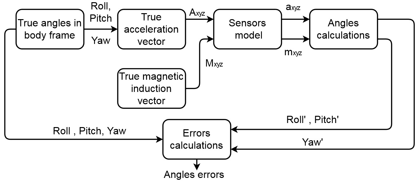
We create an arrays of random Euler angles roll, pitch, yaw. They specify sets of the true orientation of the object in the model.
我们创建一个随机的欧拉角阵列,包括横摇,纵摇和偏航。 它们指定模型中对象真实方向的集合。
我们为什么要使用这么多角度? (Why do we use so many angles?)
Errors depend on the values of the orientation angles and if we want to get an idea of the errors magnitude over the entire range then this is the easiest way.误差取决于定向角的值,如果我们想了解整个范围内的误差幅度,则这是最简单的方法。Using created angles we evaluate transformation matrixes from body frame to the local coordinate system:
使用创建的角度,我们评估从身体框架到局部坐标系的转换矩阵:
, , , , , .
, , , , , 。
Using this matrix we got an expression for true accelerations in body frame coordinate system:
使用这个矩阵,我们得到了人体框架坐标系中真实加速度的表达式:
is the vector that determines the direction of gravity expressed in units of g, is the coordinate transformation matrix from the local coordinate system to the body frame (the inverse of the transformation matrix from the body frame to the local coordinate system).
是确定以g为单位表示的重力方向的向量, 是从局部坐标系到身体坐标系的坐标变换矩阵(从身体框架到局部坐标系的变换矩阵的逆矩阵)。
Accelerometers measurements model:
加速度计测量模型:
Roll and pitch angles estimations calculated using the formulas:
使用以下公式计算的侧倾角和俯仰角:
It's also necessary to form the conversion matrix to the «horizon» from these angles. We used
还必须从这些角度形成到“地平线”的转换矩阵。 我们用了
rpy2mat (rpy2mat)
fuction:
功能:
Then we took the vector of true magnetic induction in the local coordinate system ENU and translated it to the body frame XYZ:
然后,我们在局部坐标系ENU中获取真实磁感应矢量,并将其转换为车身框架XYZ:
Magnetometers measurements model:
磁力计测量模型:
Then we recalculated the magnetometers measurements from the body frame to the «horizon»:
然后,我们重新计算了从车身框架到“地平线”的磁力计测量值:
Using the «horizontal» measurements of the magnetometers we calculated the magnetic azimuth (estimation):
使用磁力计的“水平”测量,我们计算了磁方位角(估计值):
- Orientation angles estimation errors calculated as the difference between the true angles of roll, pitch, yaw and calculated from the sensors measurements — roll', pitch', yaw'. 方位角估计误差计算为真实的侧倾角,俯仰角和偏航角之间的差,并根据传感器的测量结果计算得出-侧倾角,俯仰角,偏航角。
3.结果 (3. Results )
以下是我们以两个传感器为例的结果-ADIS16488A和MPU-9250(最大误差)。Angle | MPU-9250 | ADIS16488A |
| Roll | ||
| Pitch | ||
| Magnetic azimuth |
角度 | MPU-9250 | ADIS16488A |
| 滚 | ||
| 沥青 | ||
| 磁方位角 |
Note that this results are not a strict verdict. Results depend on supposed calibration errors. Our script should be used to get acquainted with the orientation angles estimation errors magnitude order and dependance on different input parameters.
请注意,此结果不是严格的结论。 结果取决于假定的校准误差。 我们的脚本应用于熟悉方向角估计误差的大小顺序和对不同输入参数的依赖。
加速度计和磁力计误差对方位角估计误差的影响 (Accelerometers and magnetometers errors influence on the orientation angles estimation errors)
This is how roll estimation errors depend on the roll and pitch values:
这是侧倾估计误差如何取决于侧倾和俯仰值的方式:
How pitch estimation errors depend on roll and pitch values:
俯仰估计误差如何取决于侧倾和俯仰值:
How errors of magnetic azimuth estimation depend on roll and pitch angles:
磁方位角估计的误差如何取决于侧倾角和俯仰角:
How errors of magnetic azimuth estimation depend on roll and magnetic azimuth angles:
磁方位角估计的误差如何取决于侧倾角和磁方位角:
How errors of magnetic azimuth estimation depend on pitch and magnetic azimuth angles:
磁方位角估计的误差如何取决于螺距和磁方位角:
如您所见,当接近角度范围的边界时,误差的大小会增加。 为什么? (As you can see the magnitude of the errors increases when approaching the boundary of the angles range. Why?)
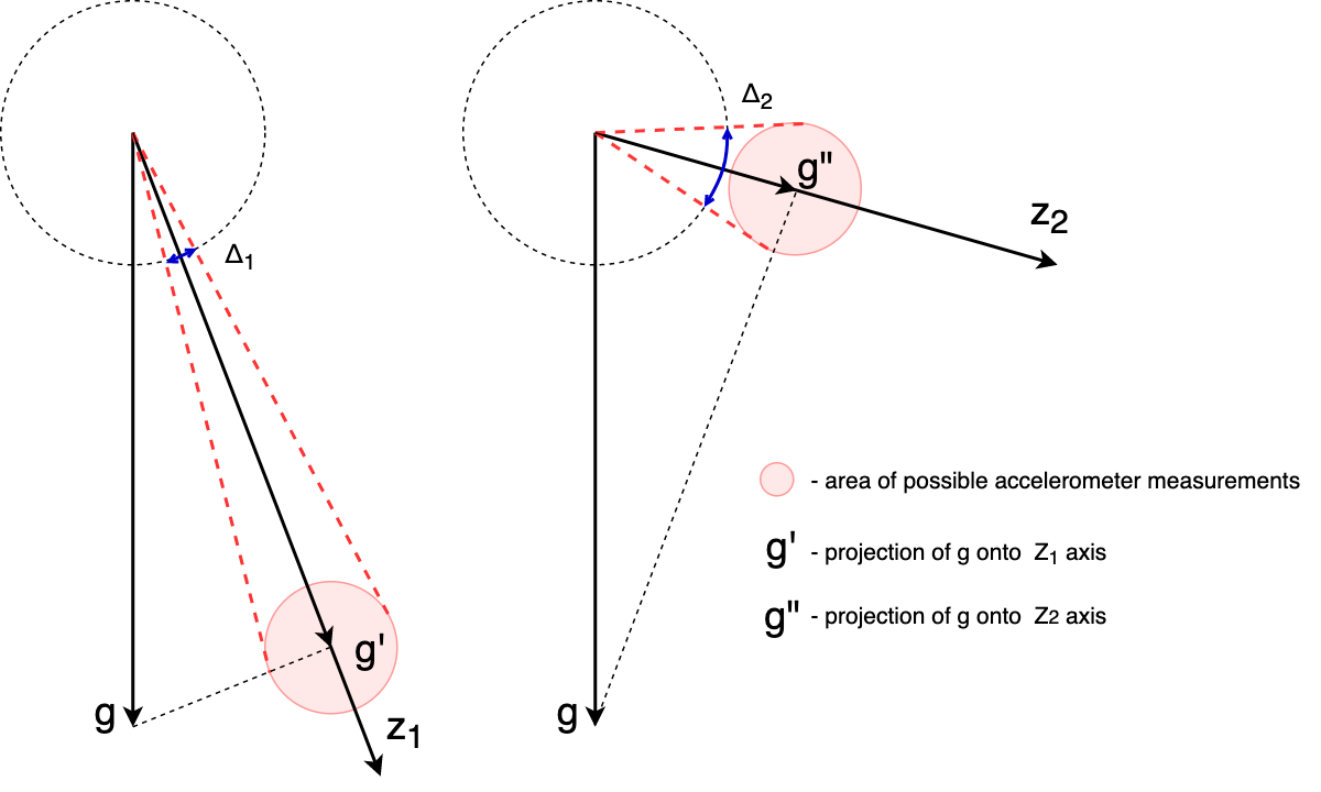
Suppose that we rotate the sensitivity axis Z
of the accelerometer so that the projection of gravity on this axis becomes smaller . The value of the gravity projection plus the error of the accelerometer will give the range of possible measurement values (pink area). Angle estimation error increases . So when gravity vector projection on the sensitivity axis decreases — constant accelerometer error begins to introduce a larger error into the angle estimate.假设我们旋转灵敏度轴Z 加速度计的角度,以使重力在该轴上的投影变小
。 重力投影的值加上加速度计的误差将给出可能的测量值范围(粉红色区域)。 角度估计误差增加 。 因此,当灵敏度轴上的重力矢量投影减小时,恒定的加速度计误差就会开始向角度估计中引入更大的误差。现在让我们使用输入参数来了解如何定义错误: (Now let's play with the input parameters to understand how the errors are defined:)
Influence of accelerometers errors ONLY on roll estimation errors depending on roll and pitch angles
加速度计误差仅对取决于侧倾角和俯仰角的侧倾估计误差的影响
Influence of accelerometers errors ONLY on pitch estimation errors depending on roll and pitch angles
加速度计误差仅对取决于倾角和俯仰角的俯仰估计误差的影响
Influence of accelerometers errors ONLY on magnetic azimuth estimation errors depending on roll and pitch angles
加速度计误差仅对取决于侧倾角和俯仰角的磁方位角估计误差的影响
Influence of accelerometers errors ONLY on magnetic azimuth estimation errors depending on roll and magnetic azimuth angles
加速度计误差仅对取决于侧倾角和磁方位角的磁方位角估计误差的影响
Influence of accelerometers errors ONLY on magnetic azimuth estimation errors depending on magnetic azimuth and pitch angles
加速度计误差仅对取决于磁方位角和俯仰角的磁方位角估计误差的影响
Influence of the ONLY magnetometers errors on orientation angles estimation errors:
仅磁力计误差对取向角估计误差的影响:
Influence of the magnetometers errors ONLY on roll estimation errors depending on roll and pitch angles
磁力计误差仅对取决于侧倾角和俯仰角的侧倾估计误差的影响
Influence of magnetometers errors ONLY on pitch estimation errors depending on roll and pitch angles
磁强计误差仅对取决于侧倾角和俯仰角的俯仰估计误差的影响
Influence of magnetometers errors ONLY on magnetic azimuth estimation errors depending on roll and pitch angles
磁强计误差仅对取决于倾角和俯仰角的磁方位角估计误差的影响
Influence of magnetometers errors ONLY on magnetic azimuth estimation errors depending on roll and magnetic azimuth angles
磁强计误差仅对取决于侧倾角和磁方位角的磁方位角估计误差的影响
Influence of magnetometers errors ONLY on magnetic azimuth estimation errors depending on pitch and magnetic azimuth angles
磁强计误差仅对取决于俯仰角和磁方位角的磁方位角估计误差的影响
摘要 (Summary)
- We have developed the Octave/MATLAB script that allows to estimate errors in the calculation of orientation angles from measurements of MEMS accelerometers and magnetometers. 我们已经开发了Octave / MATLAB脚本,该脚本允许通过MEMS加速度计和磁力计的测量来估算取向角的计算误差。
- Errors in estimating orientation angles are the functions of all orientation angles. In this case the maximum values of errors are observed at the boundaries of the selected ranges of angles. 估计方位角的误差是所有方位角的函数。 在这种情况下,在所选角度范围的边界处观察到最大的误差。
剧透-免责声明: (Spoiler - disclaimer:)
- We don't recommend buying and using these sensors (they are quite old). 我们不建议购买和使用这些传感器(它们已经很旧了)。
- We don't take into account the influence of non-linearity of measurements, the influence of vibration, instability. That's only the first approximation to the angles errors. 我们没有考虑测量非线性的影响,振动的影响以及不稳定性。 那只是角度误差的第一个近似值。
文学 ( Literature )
Tilt Sensing Using a Three-Axis Accelerometer, Rev. 6 — Freescale Semiconductor, Inc.
MPU-9250 Product Specification Revision 1.1 — InvenSense Inc.
- Perov A.I., Kharisov V.N. GLONASS. The principles of construction and functioning of M.: Radio Engineering, 2010. — 800 p. Perov AI,哈里索夫VN GLONASS。 M.的构造和功能原理:无线电工程,2010年。— 800页。
作者 ( Authors )
Nagin, Ilya — Stormgazer
- Malafeeva, Darya 达拉的马拉菲耶娃
Moscow Power Engineering Institute, Dept. of Radio Systems
莫斯科电力工程学院无线电系统系
imu和mems的差别
 402
402


 扫一扫
扫一扫


 被折叠的 条评论
为什么被折叠?
被折叠的 条评论
为什么被折叠?
 到【灌水乐园】发言


